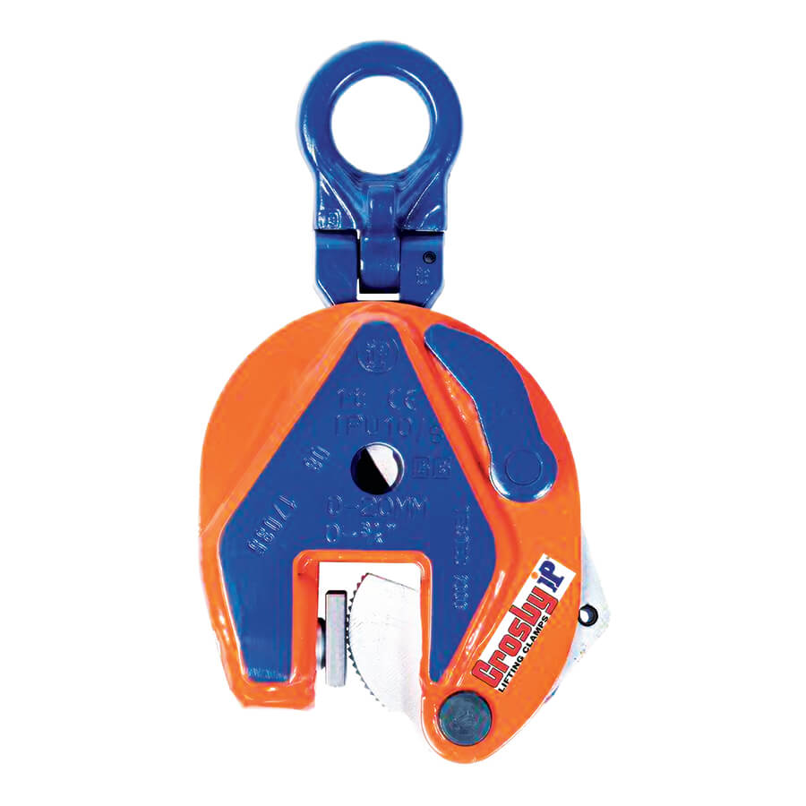
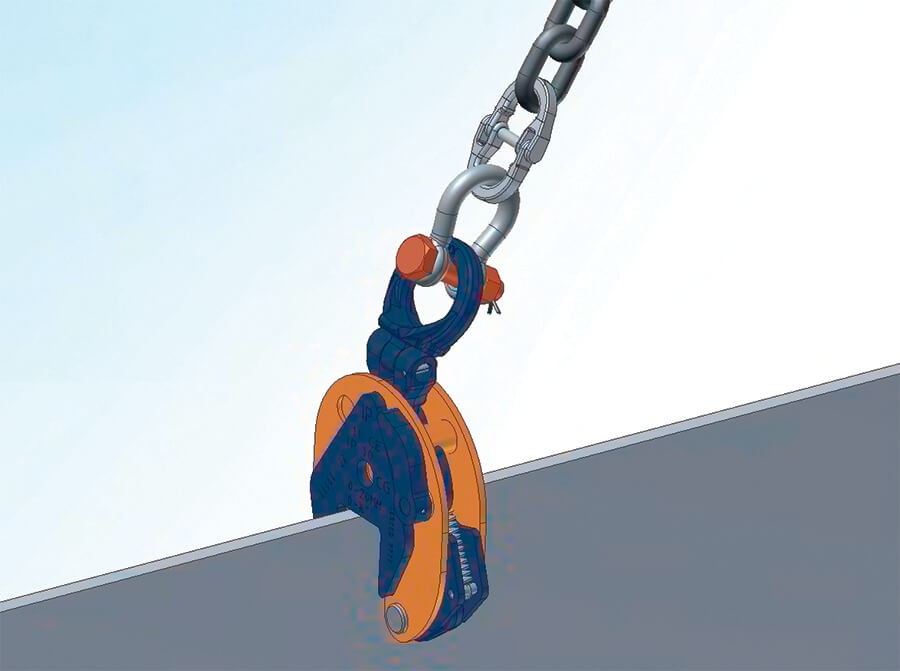
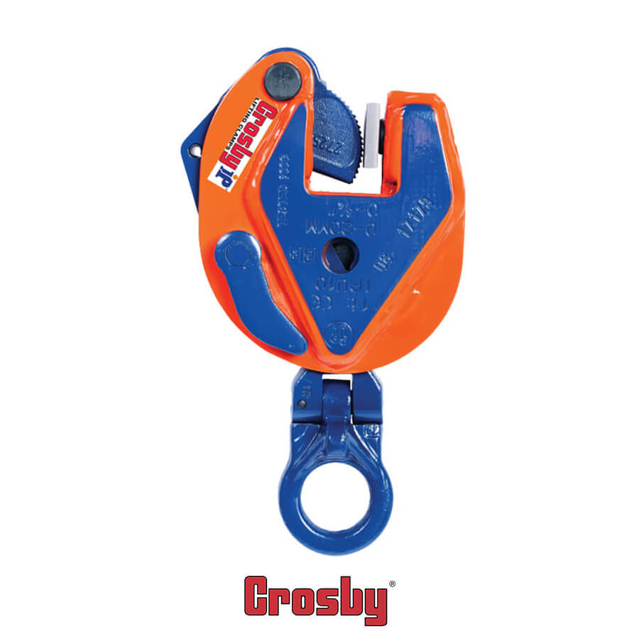
Certex Logo

Categories

Crosby® Universal Vertical Clamp Model IPU10

Crosby® Universal Vertical Clamp Model IPU10

IPU10

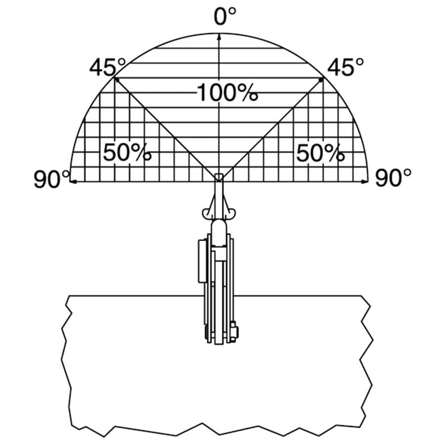
The IPU10 vertical lifting clamp is used for the lifting, turning, moving or vertical transfer of sheet, plates, or fabrications from horizontal to vertical and down to horizontal (180°) as needed. The hinged hoisting eye allows for the clamp to place and lift the load from any direction, or with a multiple leg sling without side-loading the clamp.

Model Working Load Limit (t)* IPU10 Stock No. Weight Each (lbs.) Dimensions (in.)
Jaw A B C D E F G H J K
IPU10 0.5 2701675 4.19 0 – .63 1.73 5.04 8.98 1.57 4.53 1.61 1.10 .43
IPU10 1 2701663 5.29 0 – .75 1.77 5.47 8.74 1.57 4.96 1.61 1.50 .43
IPU10 2 2701677 18.7 0 – 1.38 3.07 7.91 14.65 2.76 7.48 2.40 2.17 .63
IPU10 3 2701665 32.6 0 – 1.56 3.94 9.96 17.52 2.95 8.86 3.07 2.36 .79
IPU10 4.5 2701667 35.3 0 – 1.56 3.94 9.96 17.52 2.95 9.13 3.23 2.56 .79
IPU10 6 2701669 53.0 0 – 2.00 4.96 11.89 20.67 3.15 11.50 3.31 3.74 1.73 .79
IPU10/J 6 2702469 67.3 2.00 – 4.00 4.96 11.89 20.67 3.15 13.46 3.31 3.74 1.73 .79
IPU10 9 2701671 65.0 0 – 2.00 4.96 12.80 21.93 3.15 12.20 3.62 4.13 1.73 .79
IPU10/J 9 2701673 67.2 2.00 – 4.00 4.96 12.80 22.13 3.15 14.17 3.62 4.13 1.73 .79
IPU10 12 2701679 126 0 – 2.13 6.30 15.39 24.53 3.15 13.03 4.61 5.39 1.61 .98
IPU10/J 12 2701681 130 2.13 – 4.25 7.01 17.28 26.50 3.15 16.34 4.61 5.39 1.61 .98
IPU10 16 2701683 159 25 – 2.50 7.01 18.31 28.90 3.46 15.63 4.69 6.02 1.77 .98
IPU10/J 16 2701685 187 2.50 – 5.00 8.19 20.51 31.10 3.46 18.58 4.69 6.34 1.77 .98
IPU10 22.5 2701687 280 .25 – 3.13 8.74 21.81 33.66 4.33 18.50 5.35 7.32 1.93 .98
IPU10/J 22.5 2701689 287 3.13 – 6.13 9.96 24.72 36.61 4.33 22.64 5.35 7.72 1.93 .98
IPU10 30 2701691 337 .25 – 3.13 8.74 21.46 33.86 4.33 18.50 5.98 7.32 2.73 1.18
IPU10 30 2701693 364 3.13 – 6.13 9.84 24.41 36.81 4.33 22.24 5.98 7.72 2.13 1.18
For stainless steel – with universal hoisting eye
IPU10/S 0.5 2702275 4.19 0 – .63 1.73 5.04 8.98 1.57 4.53 1.61 1.10 .43
IPU10/S 1 2702263 4.63 0 – .75 1.77 5.47 8.74 1.57 4.96 1.61 1.50 .43
IPU10/S 2 2702277 16.8 0 – 1.38 3.07 7.91 14.65 2.76 7.48 2.40 2.17 .63
IPU10/S 3 2702265 32.7 0 – 1.56 3.94 9.96 17.52 2.95 8.86 3.07 2.36 .79
IPU10/S 4.5 2702267 35.3 0 – 1.56 3.94 9.96 17.52 2.95 9.13 3.23 2.56 .79
IPU10/S 6 2702269 53.0 0 – 2.00 4.96 11.89 20.67 3.15 11.50 3.31 3.74 1.73 .79
IPU10/S 9 2702271 65.1 0 – 2.00 4.96 12.80 21.93 3.15 12.20 3.62 4.13 1.73 .79
IPU10/S 12 2702279 67.3 0 – 2.13 6.30 15.39 24.53 3.15 13.03 4.61 5.39 1.61 .98
For very hard materials – with universal hoisting eye
IPU10/H 0.5 2702175 4.19 0 – .63 1.73 5.04 8.98 1.57 4.53 1.61 1.10 .43
IPU10/H 1 2702177 16.8 0 – 1.38 3.07 7.91 14.65 2.76 7.48 2.40 2.17 .63
IPU10/H 2 2702165 32.7 0 – 1.56 3.94 9.96 17.52 2.95 8.86 3.07 2.36 .79
IPU10/H 3 2702167 35.3 0 – 1.56 3.94 9.96 17.52 2.95 9.13 3.23 2.56 .79
IPU10/H 4.5 2702169 53.0 0 – 2.00 4.96 11.89 20.67 3.15 11.50 3.31 3.74 1.73 .79
IPU10/H 6 2702171 65.1 0 – 2.00 4.96 12.80 21.93 3.15 12.20 3.62 4.13 1.73 .79

* Design Factor based on EN 13155 and ASME B30.20.

IPU10S
IPU10S: For use on
Stainless Steel material.
IPU10H: For use on
materials with a surface
hardness to 47Rc (450 HB).


Universal – For Lifting in any Direction

  • Available in capacities of .5 thru 30 metric tons (Higher Working Load Limits are available upon request).
  • Wide variety of jaw openings available: 0” to 6.13”.
  • Welded alloy steel body for strength and smaller size. Forged alloy components, where required.
  • Individually Proof Tested to 2 times the Working Load Limit with certification.
  • Company name (CrosbyIP), logo, Working Load Limit and jaw opening permanently stamped on body.
  • Each product is individually serialized, with the serial number and Proof Load test date stamped on body.
    Serial number is included on the test certificate with maintenance and warranty logbook.
  • Full 180° turning range for material transfer, turning or moving.
  • Available in a variety of styles:
    • IPU10 – Standard clamp for materials with a surface hardness to 37Rc (345HB)
    • IPU10J – Larger jaw opening.
    • IPU10S – For use with Stainless Steel material.
    • IPU10H – For use with materials with a surface hardness to 47Rc (450HB).
  • Lock open, lock closed ability with latch for pretension on material and then release of material.
  • Optional IP-5000 Stinger assembly available (see page 420). Allows for easy connection between the clamp and hoist hook.
  • Minimum WLL of 10% of Maximum WLL.
  • Maintenance replacement kits are available.
  • Manufactured by a ISO 9001 facility
  • All sizes are RFID EQUIPPED.

WARNING: Prop 65: Products supplied by CERTEX USA may expose you to chemicals including Nickel, which is known to the State of California to cause cancer. For more information, visit to www.P65Warnings.ca.gov.

Related Products

dynarope® HF37 dynarope® Tensiometer

dynarope® HF37 dynarope® Tensiometer

The dynarope® tension meter is a precision device for measuring forces in a tensioned cable or rope. The meter can be attached directly to the cable and has a fixed display.

When the tension meter is placed on a tensioned cable, the load cell will generate a signal which is more or less proportional to the force.

The HF 37 series can be connected to a PC for managing and storing measurement results.

There is a large variety of cables, each cable having its own characteristics such as composition, diameter, rigidity, density, etc. The database includes several basic wire rope data. We are happy to help you choose the right model and parameter settings in our wire rope database.

dynarope® HF 36 – Tensiometer

dynarope® HF 36 – Tensiometer

The dynarope® HF 36 is an electronic load cell that has been designed to measure the effort applied in a wire rope. The resulting signal is used in a digital remote display (model HF 87/T/LPT) controlled by a microprocessor, which corrects the force information according to the wire rope specification and displays the result of the measurement on a LCD display.

Several wire ropes specifications are logged in a data bank.

dynasafe® HF 05 Tension Load Limiting Cell

dynasafe® HF 05 Tension Load Limiting Cell

The dynasafe® HF 05 mechanical load cell has been designed to provide a trip point in lifting systems, which have a dead-end wire rope. The trip point load limiter generates an “all or nothing” type signal in the event the programmable target value is exceeded.  Available in one or two thresholds versions.

The load cell is preferable for fitting applications where it is essential to minimize the lost headroom.

dynafor® Expert- sensor only – capacity from 1/2 t to 10 t. Accuracy: +/- 0.1% dynamometer

dynafor® Expert- sensor only – capacity from 1/2 t to 10 t. Accuracy: +/- 0.1% dynamometer

The Dynafor® Expert, designed and manufactured by Tractel, is a wireless digital dynamometer, used in high precision applications. With its unique design, it allows to reach extreme precision.
Based on the principle of strain gauge extension measurement, the sensor generates an electrical signal which is processed and analyzed by a built-in microprocessor, which transmits the information to a wireless accessory.

Equipped with radio 2.4 GHz (RF) and Bluetooth (BLE) chipsets available all time, the Dynafor® Expert provides a wireless range of 1,300 ft. (400 m) to Tractel Dynafor® HHD, large displays AL128 and software accessories 100 ft. (30 m) to any smartphone equipped with our free Dynafor® app on iOS or Android
Compatible with standard bow and clevis shackles, the Dynafor® Expert ensures a perfect implementation in your applications.