

Tackle Block Information
Calculations / Formulas
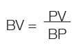
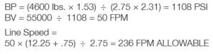
Formula for Calculating Bearing Pressure:

Formula for Calculating Bearing Velocity:
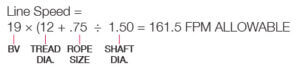
Formula for Calculating Line Speed:
![]()
Calculations can be made to find the maximum allowable line speed for a given total sheave load. If the required line speed is greater than the maximum allowable line speed calculated, then increase the shaft size and/or the hub width and recalculate. Continue the process until the maximum allowable line speed is equal to or exceeds the required line speed.
Example:
Using a 14 in. sheave (Stock # 917191; refer to wire rope sheave section of Crosby’s General Catalog for dimensions) with a 4600 lb. line pull and an 80° angle between lines determine maximum allowable line speed.


If the application required a line speed equal to 200 FPM, then another calculation would be necessary. Trying another 14 in. sheave (stock # 4104828) under the same loading conditions, the results are as follows:
Common (Plain) Bore — Very slow line speed, very infrequent use, low load.
Roller Bearing — Faster line speeds, more frequent use, greater load. Refer to manufacturer’s rating.
Loads on Blocks
The Working Load Limit (WLL) for Crosby Group blocks indicates the maximum load that should be exerted on the block and its connecting fitting. This total load value may be different from the weight being lifted or pulled by a hoisting or hauling system. It is necessary to determine the total load being imposed on each block in the system to properly determine the rated capacity block to be used. A single sheave block used to change load line direction can be subjected to total loads greatly different from the weight being lifted or pulled.
The total load value varies with the angle between the incoming and departing lines to the block.
The following chart indicates the factor to be multiplied by the line pull to obtain the total load on the block.

| Angle Factor Multipliers | |||
| Angle | Factor | Angle | Factor |
| 0º | 2.00 | 100º | 1.29 |
| 10º | 1.99 | 110° | 1.15 |
| 20º | 1.97 | 120° | 1.00 |
| 30º | 1.93 | 130° | .84 |
| 40º | 1.87 | 135° | .76 |
| 45º | 1.84 | 140° | .68 |
| 50º | 1.81 | 150° | .52 |
| 60º | 1.73 | 160° | .35 |
| 70º | 1.64 | 170° | .17 |
| 80º | 1.53 | 180° | .00 |
| 90º | 1.41 | — | — |
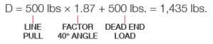
(Calculations for determining total load on single line system.)

A gin pole truck lifting 1,000 lbs.
(Calculation for determining total load value for mechanical advantage system.)
Hoisting system lifting 1,000 lbs. using a traveling block. The mechanical advantage of traveling block C is 2.00 because two (2) parts of load line support
the 1,000 lb. Weight. (To determine single line pull for various bearing efficiency see “How to Figure Line Parts.”
To Determine Line Pull:
Line Pull = 1000 lbs. ÷ 2.00 = 500 lbs.

To determine total load on snatch block A:

To determine total load on toggle block B

To determine total load on traveling block C:

To determine total load on stationary block D:
To determine total load on block E:

To determine total load on block F:
