

Rotation Resistant Wire Rope
Rotation Resistant
Wire Rope
The accepted definition of rotation resistant rope as stated in the Wire Rope Users Manual is:
ROTATION RESISTANT ROPE – a wire rope consisting of an inner layer of strands laid in one direction covered by a layer of strands laid in the opposite direction. This has the effect of counteracting torque by reducing the tendency of the finished rope to rotate.
While this properly defines the ropes, it does not tell the complete story about a commonly misunderstood and often misused product. Over the years, this type of rope has been known by various names such as Non-Rotating and Spin-Resistant. Several years ago, in order to more accurately describe the ropes and avoid confusion, they were categorized as Rotation Resistant Ropes. Bridon American produces and markets three different types of Rotation Resistant Ropes that can be grouped as follows:

Standard Rotation Resistant Ropes
19 X 7
18 X 7 FC
8 X 19 IWRC
Special Rotation Resistant Ropes
Endurance Dyform® – 18
Multiple Strand Rotation Resistant Ropes
Endurance Dyform® – 34LR
Endurance 35LS
|
19 x 7 18 x 7 FC |
8 x 19 IWRC |
DYF-18 |
34LR 35LS |
|
|---|---|---|---|---|
| Multiple Part Reeving | No | Yes | Yes | Yes |
| Single Part Reeving | Yes | Yes | Yes | Yes |
| Swivels | No | No | No | Yes |
| Strength | Low | Low | High | Highest |
| Preformed | Yes | Yes | Partially | No |
| Multiple Layer Winding | Yes | Yes | Yes | Yes |
| Prevention of Block Spinning | N/A | Good | Much Better | Best |

A 19 x 7
B 8 x 19 IWRC
C Dyform-18
D Dyform-34LR
E Endurance 35LS
Rotation Resistant Wire Rope Information
Standard Applications
Standard Applications
Mobile Cranes and Overhead Hoists 19 x 7, 18 x 7 FC, 8 x 19 IWRC
Mobile Cranes and Overhead Hoists Dyform-18
Tower Cranes and various hoisting applications Dyform-34LR and Endurance 35LS
All Rotation Resistant Ropes can be used in a variety of other applications, but the specific application and the operating requirements should be carefully reviewed by BAC Technical Services or a qualified person before a recommendation can be made.
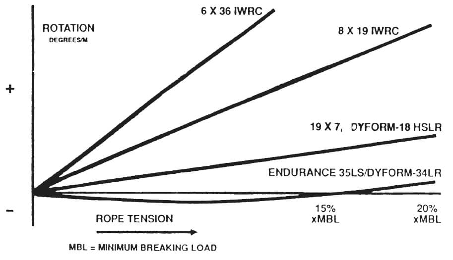
Diagramatic Illustration of Rotation
Various Rope Constructions
Seizing and Cutting
Seizing and Cutting
Because Rotation Resistant Ropes can be difficult to properly identify by sight, it is recommended that all Rotation Resistant Ropes be tightly seized with wire, strand or tape, or welded before cutting. It is important that all Rotation Resistant Ropes be prevented from unlaying when cut regardless of construction. General guidelines for seizing and welding are shown in the detail below. Endurance 35LS and Dyform-34LR should have welded ends and not seized ends.
Preformed/Non-Preformed
Preformed/Non-Preformed
Rotation Resistant Ropes are special ropes and are produced with special manufacturing techniques to meet all of the required operating parameters of the ropes. To prevent confusion as to which are preformed, partially preformed and non-preformed. Bridon American attaches a warning tag on all Rotation Resistant Ropes to indicate that they should always be properly seized when cut.
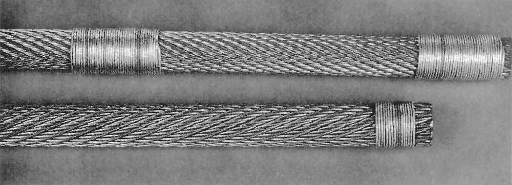
NOTE: Two seizings are recommended for non-preformed rope and one seizing for preformed rope. Each seizing should be at least one rope diameter in length.
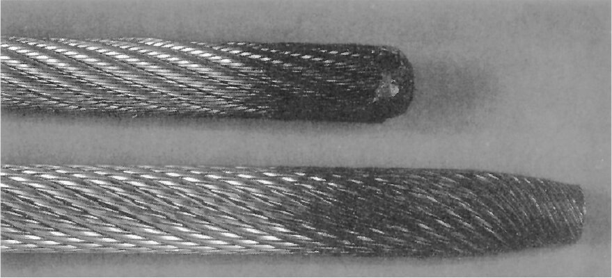
Welded Ends
Welded Ends
A welded rope end can facilitate the installation of a Rotation Resistant Rope in a wedge socket. A welded rope end combined with a tail of less than 20 rope diameters can cause rope distortion. If the proper tail length is used, a welded end is acceptable.
Top Strand: Capped Welded End
Bottom Strand: Tapered and Welded End
Handling Installation
Handling Installation
Rotation Resistant Ropes must have properly seized, or welded ends. They must be installed without inducing twist or turn. They must not be kinked, and they must have the proper tail length at the wedge socket.
Wedge Sockets
Wedge Sockets
All Rotation Resistant Ropes can be used with standard wedge sockets. Certain precautions must be taken. All Rotation Resistant Ropes should be tightly seized with wire, strand or tape, or welded to prevent loss of rope lay at the dead end. Loss of rope lay will change the operating characteristics of the ropes and can cause high strands and rope distortion.
The dead end should be a minimum length of 20 rope diameters for all Rotation Resistant Ropes. A wire rope clip may be attached to the dead end.
Swivels
Swivels 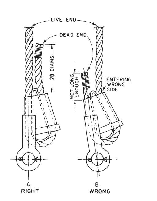
BAC’s recommendation is that 19 x 7, 18 x 7 FC,8 x 19 IWRC, and Dyform-18 should not be dead ended into a swivel. The multiple strand Rotation Resistant Ropes such as Dyform-34LR and Endurance 35LS may be used with a swivel in any application.
The reason for this recommendation is that the standard Rotation Resistant Ropes and the Special Rotation Resistant Ropes will rotate under load.
Excessive rotation will cause imbalance and reduction in strength. Under a shock load or overload condition, the strength of these ropes can be reduced as much as 50%.
BAC does recognize that there are certain applications or operating requirements where a swivel must be used with Rotation Resistant Ropes. In these cases, it is mandatory that the design factor be strictly followed, the ropes are not shock loaded, and the ropes are frequently inspected by a qualified person. BAC recommends that each application requiring the use of a swivel with Standard or Special Rotation Resistant Ropes be reviewed and approved by a qualified person.
There has been some confusion about swivels attached between the rope and the dead end attachment point and swivels below the traveling block (between the block and the load). For the purpose of the previous discussion, we are referring to the swivel attachment between the rope and the dead end attachment point. Most swivels below the traveling block are not antifriction ball bearing swivels.
Multiple Part Reeving
Multiple Part Reeving
19 x 7 and 18 x 7 FC ropes are not recommended for multiple part reeving. These ropes do not perform well and tend to become imbalanced when used in this manner. The 8 x 19 IWRC ropes, Dyform-18, Dyform-34LR, and Endurance 35LS are more stable constructions and can be used in multiple part reeving.
Single Part Hoisting
Single Part Hoisting
All Rotation Resistant Ropes can be used in single part hoisting. However, the limitations of single part hoisting must be understood. Rotation Resistant Ropes will develop torque when a load is applied and rotation of the load can occur. The amount of rotation depends on many factors.
If the loads being handled under all operating conditions are within the recommended design factors, the amount of rotation should not cause problems. If the rope is shock loaded or loaded beyond the recommended design factor,rotation of the rope will be a problem. As stated previously, when Rotation Resistant Ropes rotate, the strength of the rope is reduced. If the rotation is severe enough, the rope can fail or rapidly develop broken wires and wear in the inner rope where it can be difficult to detect.
Odd Part Reeving
Odd Part Reeving
Odd part reeving such as 3, 5 or 7 part can cause problems if the traveling block is not properly aligned. While a greater number of parts reeved in an even number will require slower hoisting speeds, it can prevent problems. If odd part reeving is necessary, the dead end at the traveling block should be attached to the center of the block rather than at the side of the block. (see below).An odd part reeving system can cause the traveling block to be suspended and hang at an angle. This misalignment will induce twist into the rope during operation by the rope climbing the flange or rolling into the sheaves of the traveling block during hoisting.
Fleet Angles
Fleet Angles
Because Rotation Resistant Ropes develop less torque under load than a standard 6 strand rope, there can be a problem with rope pileup and poor spooling unless a proper fleet angle is maintained. The fleet angle becomes even more important with the very low torque ropes such as Dyform-34LR and Endurance 35LS. A fleet angle of 1/2° to 1-1/2°is recommended for Rotation Resistant Ropes.
Cabling Graph
Cabling Graph
Field research jointly conducted by the Wire Rope Technical Board and the Power Crane and Shovel Association has shown that cabling of the rope parts in a multiple part reeved hoisting arrangement is controlled by several factors. The following calculations and graphs can be used to determine when and if cabling will occur on multiple part reeved hoisting arrangements.
The graph illustrates two dimensional ratios. They are:
L/S = Length of fall per unit rope spacing
D/d = Average pitch diameter of traveling and crown block sheave per unit rope diameter.
Various constructions of rope shown on the graph indicate the limited conditions for torsional stability with the angular displacement of the hoist block to a maximum of 90 degrees. When the operating conditions for a particular installation give a resultant above the appropriate band, then cabling of the falls will most likely occur. If the operating conditions give a resultant below any particular band, the cabling of the falls will most likely not occur. If the operating conditions for any particular installation fall within the band, cabling is unpredictable.
*19 x 7 is shown in this band for information only. 19 x 7 is not recommended for multiple part reeving.
Retirement Criteria
Retirement Criteria
Recommended retirement criteria for all Rotation Resistant Ropes are 2 broken wires in 6 rope diameters or 4 broken wires in 30 rope diameters. (i.e. 6 rope diameters for a 1” diameter rope = 6”).
Distortion of Rotation Resistant Ropes, as shown above, can be caused by shock load/sudden load release and/or induced torque and is the reason for immediate removal from service.
Recommended Minimum Sheave and Drum Diameters
Recommended Minimum Sheave and Drum Diameters
The minimum D/d ratio allowed by applicable codes and standards covering equipment where Rotation Resistant Ropes are typically used is 18:1.
Recommended Minimum Design Factor
Recommended Minimum Design Factor
The minimum design factor allowed by applicable codes and standards covering equipment where Rotation Resistant Ropes are typically used is 5.
WARNING: Any warranties, expressed or implied, concerning the use of this product apply only to the nominal strength of new, unused wire rope. All equipment using this product must be properly used and maintained. Wire rope must be properly stored, handled, used and maintained. Most importantly, wire rope must be regularly inspected during use. Damage, abuse or improper maintenance can cause rope failure. Consult the AISI Wire Rope Users Manual, ASME or ANSI Standards, before usage. Wire rope removal criteria are based on the use of steel sheaves. If synthetic sheaves are used, consult the sheave equipment manufacturer. WARNING!