WIRE ROPE SLING RESOURCES
Definitions & Nomenclature
Wire Rope Slings
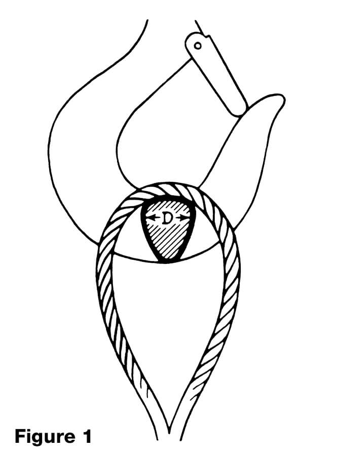
NOMINAL SLING STRENGTH is based upon the nominal (catalog) rope strength of the wire rope used in the sling and other factors which affect the overall strength of the sling. These other factors include splicing efficiency, number of parts of rope in the sling, type of hitch (e.g., straight pull, choker hitch, basket hitch, etc.), diameter around which the body of the sling is bent (D/d) and the diameter of pin used in the eye of the sling (Figure 1).
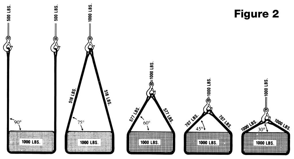
SLING ANGLE is the angle measured between a horizontal line and the sling leg or body. This angle is very important and can have a dramatic effect on the rated capacity of the sling. As illustrated (Figure 2), when this angle decreases, the load on each leg increases. This principle applies whether one sling is used to pull at an angle, in a basket hitch or for multi-legged bridle slings. Sling angles of less than 30 degrees are not recommended.
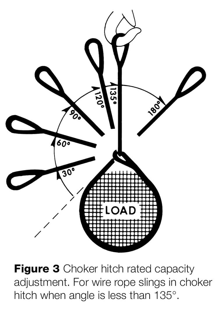
CHOKER HITCH configurations affect the rated capacity of a sling. This is because the sling leg or body is passed around the load, through one end attachment or eye and is suspended by the other end attachment or eye. The contact of the sling body with the end attachment or eye causes a loss of sling strength at this point. If a load is hanging free, the normal choke angle is approximately 135 degrees. When the angle is less than 135 degrees an adjustment in the sling rated capacity must be made (Figure 3).
| TABLE 1 | |
| CHOKER HITCH RATED CAPACITY ADJUSTMENT |
|
| ANGLE OF CHOKE IN DEGREES |
RATED CAPACITY IWRC IWRC AND FC ROPE PERCENT”‘ |
| OVER 120 | 100 |
| 90·120 | 87 |
| 60-89 | 74 |
| 30· 59 | 62 |
| 0· 29 | 49 |
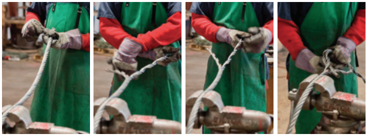
NOMINAL SPLICE EFFICIENCY is the efficiency of the sling splice. Any time wire rope is disturbed such as in splicing an eye, the strength of the rope is reduced. This reduction must be taken into account when determining the nominal sling strength and in calculating the rated capacity. Each type of splice has a different efficiency, thus the difference in rated capacities for different types of slings. Nominal splice efficiencies have been established after many hundreds of tests over years of testing.
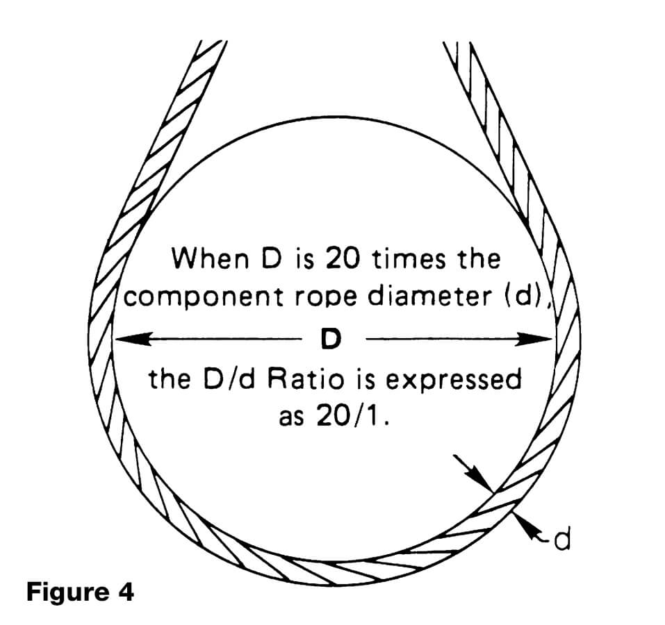
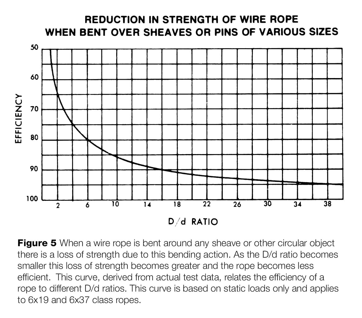
D/d ratio is the ratio of the diameter around which the sling is bent divided by the body diameter of the sling (Figure 4). This ratio has an effect on the rated capacity of the sling only when the sling is used in a basket hitch. Tests have shown that whenever wire rope is bent around a diameter, the strength of the rope is decreased. Figure 5 illustrates the percentage of decrease to be expected. This D/d ratio is applied to wire rope slings to assure that the strength in the body of the sling is at least equal to the splice efficiency. When D/d ratios smaller than those listed in the rated capacity tables are necessary, the rated capacity of the sling must be decreased.
RATED CAPACITY is the maximum static load a sling is designed to lift. The tables give rated capacities in tons of 2000 pounds. Rated capacities contained in all the tables were calculated by computer. Each value was calculated starting with the nominal component rope strength and working up from there. Due to computer rounding of numeric values, rated capacity values for 2, 3 or 4 leg slings may not be even multiples of single leg values and may differ by a small amount. This represents the state-of-the-art technology and tables found in other publications which differ by this small amount should not be construed to be in error. The difference is generally no more than one unit for any sling diameter.
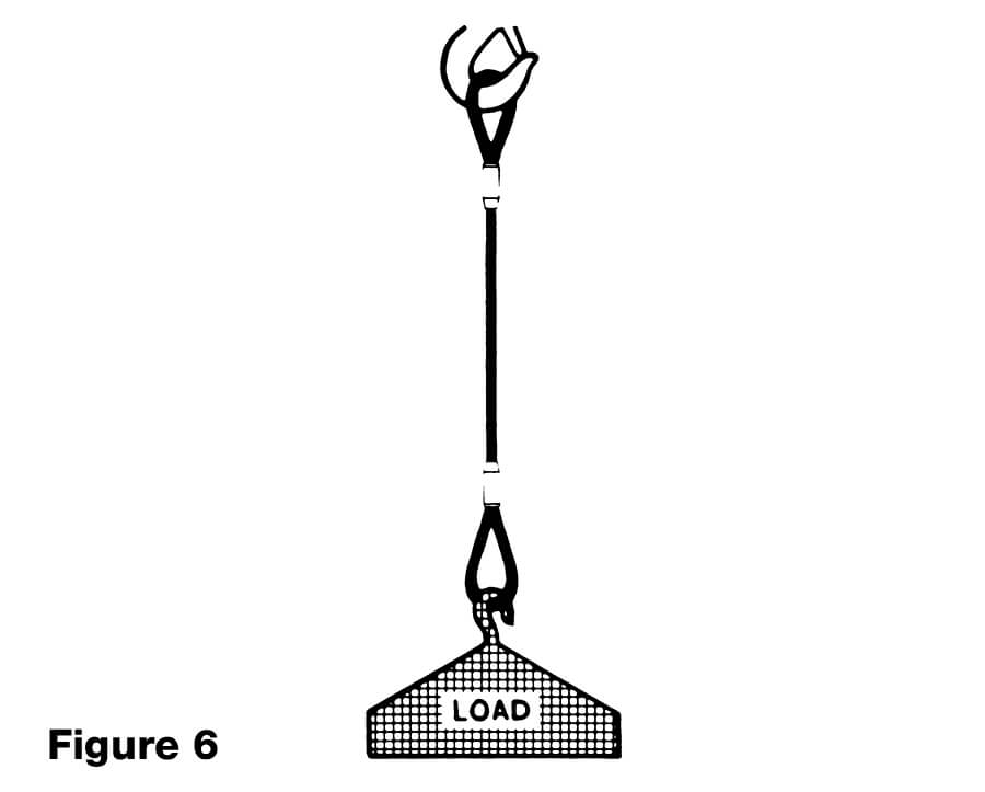

PROOF LOAD is a specific load applied to a sling or assembly in a non-destructive test to verify the workmanship of the sling. All swaged socket or poured socket assemblies should be proof loaded. The proof load is generally two (2) times the vertical rated capacity for mechanical splice slings. The maximum proof load for hand tucked slings is 1.25 times the vertical rated capacity. Care should be taken to assure that sling eyes are not damaged during the proof load.
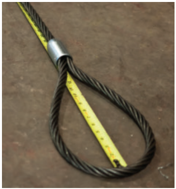
EYE DIMENSIONS are generally eight (8) sling body diameters wide by sixteen (16) body diameters long. Whenever possible thimbles are recommended to protect the rope in the sling eye. Eye dimensions for thimbles are contained in table 2. Table 2 contains only dimensions for thimbles used in standard single part slings. Other specialized thimbles are available. Consult your sling manufacturer for details.
PIN DIAMETER should not be any greater than the natural width of the sling eye. For any sized eye and type of sling body, the maximum allowable pin diameter may be calculated as follows:
Maximum pin diameter = (2L + W) x 0.2
Where
L = length of eye
W = width of eye
The minimum pin diameter should never be smaller than the nominal sling diameter.
GRADE & CONSTRUCTION of wire rope for slings is generally accepted to be bright Improved Plow Steel or Extra Improved Plow Steel grade 6×19 or 6×37 classification regular lay. IWRC rope has a higher rated capacity than Fiber Core rope for mechanically spliced slings, but the same rated capacity for hand tucked slings. This is because when making a hand tucked splice, the core (IWRC) of the rope is cut in the splice area and doesn’t add to the overall strength of the sling. Rated capacities of slings using galvanized rope depend on the method of galvanizing. The sling manufacturer should be consulted regarding rated capacities for these types of slings.
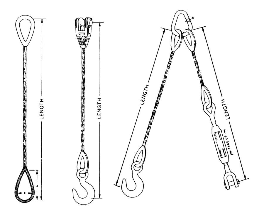
MINIMUM SLING BODY LENGTH is the minimum length of wire rope between splices, sleeves or fittings. Generally the minimum body length is equal to ten (10) times the sling body diameter. This allows approximately one and one half (1 1/2) rope lays between splices. For multi-part slings the minimum body length between splices is equal to forty (40) times the component rope diameter.
LENGTH TOLERANCE is generally plus or minus two (2) body diameters, or plus or minus 0.5% of the sling length, whichever is greater. The legs of bridle slings, or matched slings are normally held to within one (1) body diameter. Tolerances on poured or swaged socket assemblies are generally much closer. Tolerances should always be specified to the sling manufacturer before the order is placed. This eliminates a lot of frustration and confusion later.

