WIRE ROPE SLING RESOURCES
Splicing – Wire Rope Slings
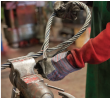
Hand Tucked Splice
A hand tucked splice is made by passing the wire rope around a thimble or forming an eye and splicing the dead end (short end) into the live end (long end) of the rope. Normally, each dead end strand is given one forming tuck and three full tucks around the same strand in the body of the rope. One additional full tuck is made when splicing more pliable wire ropes such as 6×37 classification.
A “forming tuck” is made by prying two adjacent strands apart, inserting a dead end strand into the opening and passing the strand under one, two, or three adjacent strands in the body of the rope. The dead end strand is set or locked tightly.
A “full tuck” is made by inserting a dead end strand under and rotating it one full 360 degree turn around a strand in the body of the wire rope. The tucked strand is set or locked tightly. Each subsequent full turn of the dead end strand around the live end strand constitutes an additional full tuck.
“Setting” or “locking” of a dead end strand is accomplished by pulling the strand end in under considerable force. A marlin spike is inserted in the same opening in the body of the rope ahead of the tucked strand and is rotated about the axis of the rope back to the start of the splice or toward the previous tuck. This helps set the tuck.
Certain end usages may indicate the desirability of special splices such as the Navy Admiralty Splice or logging splice. Splices made by these special methods may also attain the efficiencies used in calculating the rated capacity tables where the rope quality and number of tucks are equivalent to that outlined above. Development of such efficiencies should be confirmed by the sling fabricators making such splices.
Serving or wrapping of wire rope sling splices does not affect the splicing efficiencies nor rated capacities. Such servings are optional, although unserved splices are preferred because they permit visual inspection of the spliced area.
NOMINAL SPLICE EFFICIENCIES are measured in terms of efficiency (where efficiency = actual breaking strength of spliced termination divided by actual breaking strength of rope). This efficiency will change from splice to splice because of the many variable factors involved in producing the splice. Splice efficiencies given in Table 3 were established so that these normal variations are accommodated. The design factor used in establishing the rated capacities further assures that the sling will lift the load even in those rare instances when the splice efficiency falls slightly below the values given in the tables. Rated capacities shown in this manual have met with the most exacting test, that of the test of time and use in over fifty years of actual field experience.
| TABLE 3 | |||
| NOMINAL SPLICE EFFICIENCIES HAND TUCKED SPLICE IPS AND EIPS IMPROVED PLOW STEEL AND EXTRA IMPROVED PLOW 6X19 & 6X37 CLASS ROPES |
|||
| Rope Dia. | Nominal Eff. Factor |
Rope Dia. | Nominal Eff. Factor |
| 1/4 | .90 | 1 1/4 | .80 |
| 5/16 | .89 | 1 3/8 | .80 |
| 3/8 | .88 | 1 1/2 | .80 |
| 7/16 | .87 | 1 5/8 | .80 |
| 1/2 | .86 | 1 3/4 | .80 |
| 9/16 | .85 | 1 7/8 | .80 |
| 5/8 | .84 | 2 | .80 |
| 3/4 | .82 | 2 1/8 | .80 |
| 7/8 | .80 | 2 1/4 | .80 |
| 1 | .80 | 2 3/8 | .80 |
| 1 1/8 | .80 | 2 1/2 | .80 |
GENERAL PRECAUTIONS for hand tucked slings are about the same as for any other type of sling. The use of a swivel on single leg lifts as well as free hanging loads which may rotate is not recommended. A tag line should always be used to prevent rotation of the sling body. When the sling body of a hand tucked splice is allowed to rotate, the splice could unlay and pull out, thus causing the load to drop.

Mechanical Splice
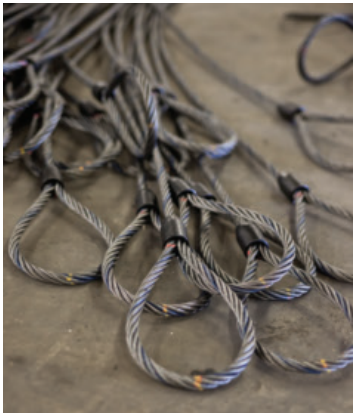
Mechanical splice slings come in two basic types. One being the Returned Loop and the other the Flemish Eye or farmers splice. In either case, the splice is completed by pressing (swaging) one or more metal sleeves over the rope juncture.

The returned loop is fabricated by forming a loop at the end of the rope, sliding one or more metal sleeves over the short end of the loop eye and pressing these sleeves to secure the end of the rope to the sling body. This makes an economical sling and in most cases one that will give satisfactory service. A drawback to this type of sling is that the lifting capacity of the sling depends 100% upon the integrity of the pressed or swaged joint. Should the metal sleeve(s) fail, the entire eye will also fail.
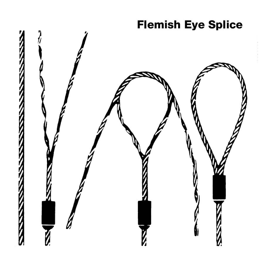
The flemish eye splice is fabricated by opening or unlaying the rope body into two parts, one having three strands and the other having the remaining three strands and the core. The rope is unlayed far enough back to allow the loop or eye to be formed by looping one part in one direction and the other part in the other direction and laying the rope back together. The strands are rolled back around the rope body. A metal sleeve is then slipped over the ends of the splice and pressed (swaged) to secure the ends to the body of the sling. Nominal splice efficiencies expressed in table 4 and in the rated capacity tables are based on this splicing method. Splice efficiencies for other splicing methods should be confirmed by the sling manufacturer.
Notice that the splice efficiency factor plays no role in the calculation of the Choker Hitch rated capacity. This is because as the rope passes through the eye of the sling in a choke, the weakest part of the sling is in the body of the sling at the choke point. Thus the splice being higher in efficiency, has no effect on the rated capacity, because the efficiency factors are not additive.
Rated capacities for single part, choker and basket hitches are calculated exactly the same as for hand tucked slings except for the nominal splice efficiencies. The rated capacities adjustment table 1 for choker hitches also applies for mechanical splice slings. Minimum D/d ratio for basket hitches is 25. This larger D/d ratio is required because the Nominal Splice Efficiency is higher.
GENERAL PRECAUTIONS are no different from other slings except care should be taken not to deform or damage the sleeve. Stainless Steel slings which have sleeves made of a different grade or type metal than the rope body may experience accelerated deterioration due to an electrochemical reaction between the two metals. This is particularly evident in salt water or brackish conditions.
| TABLE 4 | ||
| NOMINAL SPLICE EFFICIENCIES MECHANICAL SPLICED SLINGS IMPROVED PLOW STEEL |
||
| DIAMETER | IWRC | FIBER CORES |
| 1/4 through 1″ | .95 | .925 |
| 1 1/16 through 2″ | .925 | .90 |
| 2 1/16 & larger | .90 | Not Established |
| EXTRA IMPROVED PLOW STEEL: | ||
| 1/4 through 1″ | .95 | |
| 1 1/16 through 2″ | .925 | |
| 2 1/16 & larger | .90 | |
| STAINLESS STEEL, 302 & 304 Grade: | ||
| 1/4 through 1″ | .95 | |
| 1 1/16 through 2″ | .925 | |
| 2 1/16 & larger | .90 | |


