WIRE ROPE TERMINATION Resources
Spelter Sockets
General Guidelines

Figure 8

Figure 9

Figure 10
Zinc-Poured Spelter Socketing
1. Measure the Rope Ends to be Socketed
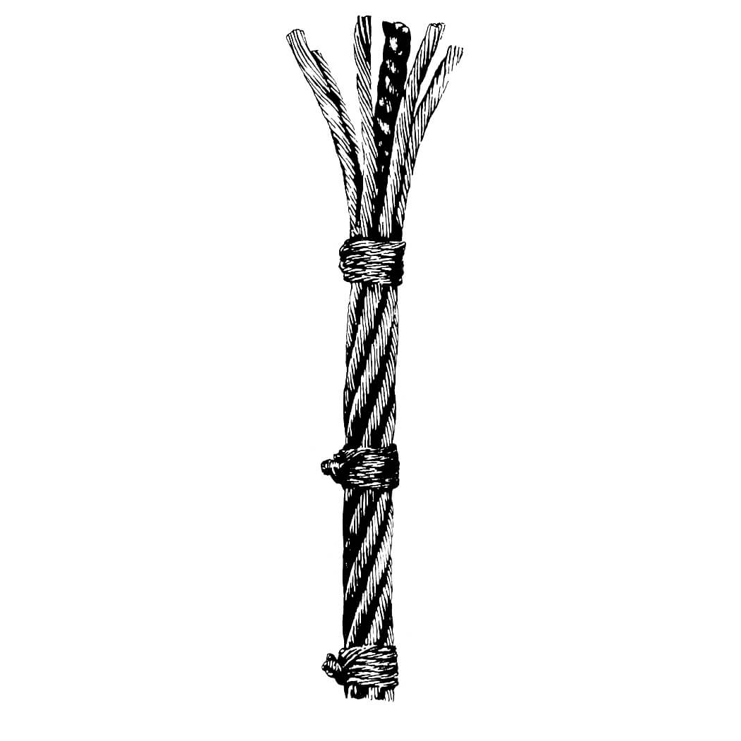
The rope end should be of sufficient length so that the ends of the unlaid wires (from the strands) will be at the top of the socket basket. (Fig. 8)
2. Apply Serving at Base of Socket
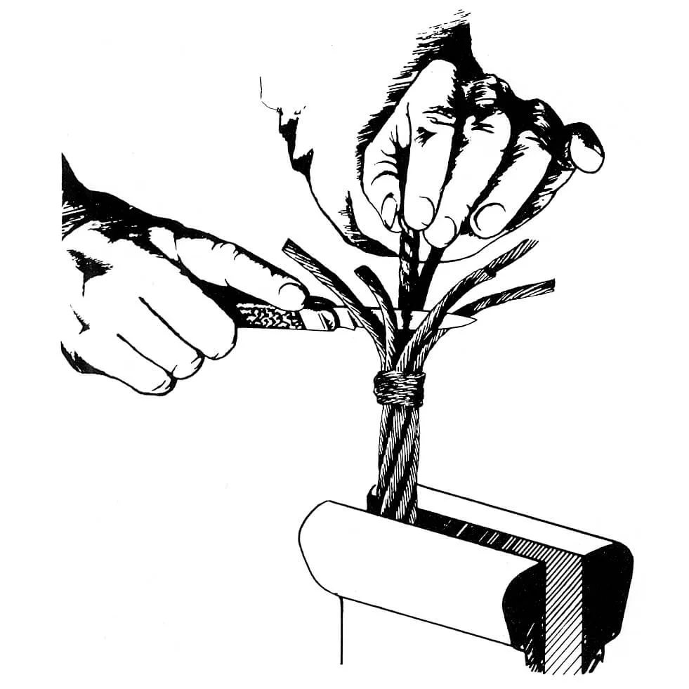
Apply a tight wire serving band, at the point where the socket base will be, for a length of two rope diameters. (Figs. 9 & 10)
3. Broom Out Strand Wires
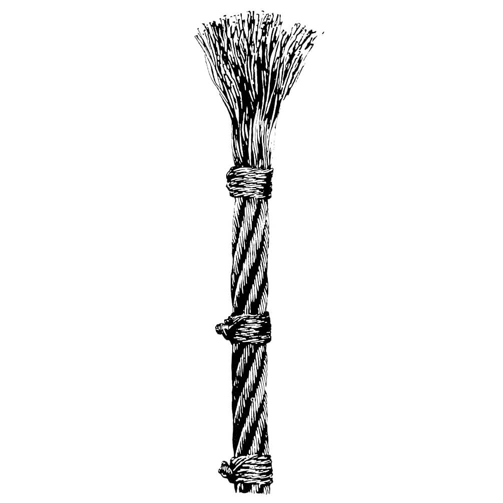
Unlay and Straighten the individual rope strands and spread them evenly so that they form an included angle of approximately 60 degrees. Unlay the wires of each individual strand for the full length of the rope end—being careful not to disturb or change the lay of the wires and strands under the serving band. Unlay the wires of the independent wire rope core (IWRC) in the same manner. A fiber core should be cut out and removed as close to the serving band as possible. (Fig. 9)
4. Clean the Broomed-Out Ends
A suggested cleaning solvent for this step is SC-5 Methyl Chloroform or equivalent solvent. These are known under the names Chlorothane VG, 1-1-1 Trichlorethane, Perchloroethane, and Perchloroethylene.
Swish the broomed-out rope end in the solvent, then brush vigorously to remove all grease and dirt—making certain that the wires are clean to the very bottom of the broom up the serving band (Fig. 11). Additionally, a solution of muriatic acid may also be used. If acid is used, the broomed-out ends should be rinsed in a solution of bicarbonate of soda so as to neutralize any acid that may re-main on the rope. Care should be exercised to prevent acid from entering the core; this is particularly important if the rope has a fiber core. Where it is feasible, the best and preferred cleaning method for rope ends
prior to socketing is ultrasonic cleaning. After this cleaning step, place the broomed-out end pointing downward, allowing it to remain until all solvent has evaporated and the wires are dry.
Solvent should never be permitted to remain on the rope or on the serving band since it will run downthe wires when the rope is turned upright.
Figure 11
Figure 12
Figure 13
. Dip the Broomed-Out Rope Ends in Flux
Prepare a hot solution of zinc-ammonium chloride flux comparable to Zaclon K. Use a concentration of 1 lb. of zinc-ammonium chloride to 1 gallon of water; maintain the solution at a temperature of 180 degrees to 200 degrees F. Swish the broomed-out end in the flux solution, then point the rope end downward until such time as the wires have dried thoroughly (Fig. 12).
6. Close Rope Ends and Place Socket
Use clean seizing wire to compress the broomedend into a tight bundle which will permit the socket to be slipped easily over the wires (Fig. 13). Before placing the socket on the rope, make certain the socket is clean and no moisture is present inside the bowl of the socket. Heating the socket will dispel any residual moisture and will also prevent the zinc from freezing or cooling prematurely.
A word of caution: Never heat a socket after it is placed on the rope. To do so may cause damage to the rope.
After the socket is on the rope, the wires should be distributed evenly in the socket basket so the zinc can surround each wire. Use extreme care in aligning the socket with the rope’s centerline, and in making certain there is a minimum vertical length of rope extending from the socket equal to about 30
rope diameters. This vertical length is necessary for rope balance. Premature wire breaks at the socket can occur if the rope is not balanced at pouring.
Seal the socket base with fire clay or putty but make certain the material does not penetrate into the socket base. Should this occur, it could prevent the zinc from penetrating the full length of the socket basket thereby creating a void that would collect moisture after the socket is placed in service (Fig. 14).
7. Pour the Zinc
The zinc used should meet ASTM Specification designation B6-49 Grade (1) Prime Western or better, and Federal Specification QQ-Z351-a Amendment 1, interim Amendment 2. Pour the zinc at a temperature of 950 degrees to 1000 degrees F (Fig. 15). A word of caution: Overheating of the zinc may affect its bonding properties. The zinc temperature may be measured with a portable pyrometer or a Tempilstik. Remove all dross from the top of the zinc pool before pouring. Pour the zinc in one continuous stream until it reaches the top of the basket and all wire ends are covered; there should be no “capping” of the socket.
8. Remove Serving
After the zinc and socket have cooled remove the serving band from the socket base and check to make certain that the zinc has penetrated to the socket base (Fig. 16).
9. Lubricate the Rope
Apply wire rope lubricant to the rope at the base of the socket and on any rope section where the original lubricant may have been removed.
Figure 14
Figure 15
Figure 16
Thermo-Set Resin Socketing
Before proceeding with a thermo-set resin socketing procedure, check the resin manufacturer’s instructions carefully. Each resin system has specific procedures and steps which must be followed in the order specified for the system to give the desired results. Since any thermo-set resin system depends upon chemical reaction, the procedure becomes critically important.
Give particular attention to selecting sockets designed for resin socketing. The following steps give a general outline to follow for resin socketing, they should not be used as a substitute for detailed instructions supplied by the resin manufacturer.
1. Measure the Rope Ends to be Socketed
The rope end should be of sufficient length so the ends of the unlaid wires (from the strands) will be at the top of the socket basket. (Fig. 8)
2. Apply Serving at Base of Socket
Apply a tight wire serving band, at the point where the socket base will be, for a length of two rope diameters. (Figs. 9 & 10)
3. Broom Out Strand Wires
Unlay and straighten the individual rope strands and spread them evenly so that they form an included angle of approximately 60 degrees. Unlay the wires of each individual strand for the full length of the rope end—being careful not to disturb or change the lay of the wires and strands under the serving band. Unlay the wires of the independent wire rope core (IWRC) in the same manner. A fiber core should be cut out and removed as close to the serving band as possible. (Fig. 9)
4. Clean the Broomed-Out Ends
A suggested cleaning solvent for this step is SC-5 Methyl Chloroform or equivalent solvent. It is also known under the names Chlorothane VG, 1-1-1 Trichlorethane, Perchlorothane, and Perchloroethylene.
CAUTION: Breathing the vapor of this solvent is harmful; it should only be used in a well-ventilated area. Be sure to follow the solvent manufacturer’s instructions, and carefully observe all instructions printed on the label.
Swish the broomed-out rope end in the solvent, then brush vigorously to remove all grease and dirt—making certain that the wires are clean to the very bottom of the broom up to the serving band (Fig. 11). The use of acid to etch the wires before resin socketing is unnecessary and not recommended. Also, the use of flux on the wires before pouring resin should be avoided since this adversely affects resin bonding to the steel wires. Where it is feasible, the best and preferred cleaning method for rope ends prior to socketing is ultrasonic cleaning. After this cleaning step, place the broomed-out end pointing downward allowing it to remain until all solvent has evaporated and the wires are dry.
Solvent should never be permitted to remain on the rope or on the serving band since it will run down the wires when the rope is turned upright.
Close Rope Ends and Place Socket
Place rope in a vertical position with the broom end up. Close and compact the broom to permit insertion of the broomed end into the base of the socketing. Slip the socket on, removing any temporary banding or seizing as required. Make certain the broomed wires are uniformly spaced in the basket, with the wire ends slightly below the top edge of the basket, and the axis of the rope and the fitting are aligned. Seal the annular space between the base of the socket and the rope to prevent leakage of the resin from the basket. In addition to normal sealing materials, non-hardening butyl rubber-base sealant or latex glazing compounds are satisfactory for this purpose. Make sure the sealant does not enter the base of the socket so the resin will be able to fill the complete depth of the socket basket.
6. Pouring the Resin
Mix and pour the resin in strict accordance with the resin manufacturer’s instructions.
7. Lubrication After Socket Attachment
After the resin has cured, re-lubricate the wire rope at the base of the socket to replace any lubricant that may have been removed during the cleaning operation.
8. Acceptable Resin Types
Properties of commercially available resins vary considerably. It is next to impossible to establish general rules to cover all available resins. It is extremely important to refer to the individual resin manufacturer’s instructions before using any one type. If the resin manufacturer has no data as to how his resin system preforms with wire rope socketing, tests should be conducted before the system is used for field applications.
When properly formulated, most thermoset resins are acceptable for socketing. These formulations, when mixed, form a pourable material which will harden at ambient temperature, or upon the application of moderate heat. No open flame or molten metal hazards exist with resin socketing since heat-curing when necessary, requires a relatively low temperature (250-300 degrees F) obtainable by electric resistance heating. Since resin socketing is so much simpler than zinc socketing, care must be taken not to become lax in following the recommended procedures.
Tests have demonstrated that satisfactory wire rope socketing performance can be obtained with resins having characteristics and properties as follows:
The resin shall be a liquid thermoset material that will harden after being mixed with the correct proportion of catalyst or curing agent. (Hardener)
A. Properties of Liquid (Uncured) Material
Resin and catalyst are normally supplied in two separate containers. After thoroughly mixing the two components together, the liquid can be poured into the socket basket. For ease of handling, liquid resins and catalysts should have the following properties:
1. Viscosity of the resin-catalyst mixture should be 30-40,000 CPS at 75 degrees F immediately after mixing. The viscosity will increase at lower ambient temperature and the resin may require warming prior to mixing with the catalyst if ambient temperatures are too low.
2. Flash Point
Both resin and catalyst should have a minimum flash point of 100 degrees F.
3.Shelf Life
Unmixed resin and catalyst should have a maximum shelf life specified by the resin manufacturer.
4.Pot Life and Cure Time
After mixing, the resin-catalyst blend should be pourable for approximately eight minutes and should harden within 30 minutes. Heating the blend in the socket should be permissible to obtain the cure.
B. Properties of the Cured Resin
1. Socket Performance
The resin shall exhibit sufficient bonding to the solvent-washed wires in a wire rope end socket to develop the breaking strength of all types, constructions and grades of wire rope. No slippage of individual wires is permissible when testing resin socketed rope assemblies in tension. After testing, however, some “seating” of the resin cone may be apparent and is acceptable.
The resin/wire bond within the cone or basket must be capable of withstanding tensile-shock loading encountered in normal field usage.
2. Compressive Strength
The minimum allowable compressive strength for fully cured resin is 12000 psi.
3.Shrinkage
Maximum allowable shrinkage is 2%. To control shrinkage, an inert filler may be used in the resin provided that the viscosity requirements are met. This filler material should always be formulated into the resin system by the resin manufacturer, not field mixed by the user.
4. Hardness
The desired hardness of the cured resin system is in the range of Barcol 40-55.
C. Performance of Resin Socketed Assemblies
Resin socketed assemblies may be moved after the resin has hardened. If the resin manufacturer’s
directions are followed, resin sockets should develop the breaking strength of the rope, and have the capability to withstand shock loading to a degree sufficient to break the rope, without the resin cone cracking or breaking.
One final note: resin technology is changing almost daily. Characteristics of these products vary significantly and each must be handled differently. The resin manufacturer should supply specific data as to fitness of their system for wire rope socketing.
