MATCHING THE WIRE ROPE WITH SHEAVES & DRUMS
Matching the Wire Rope with Sheaves and Drums

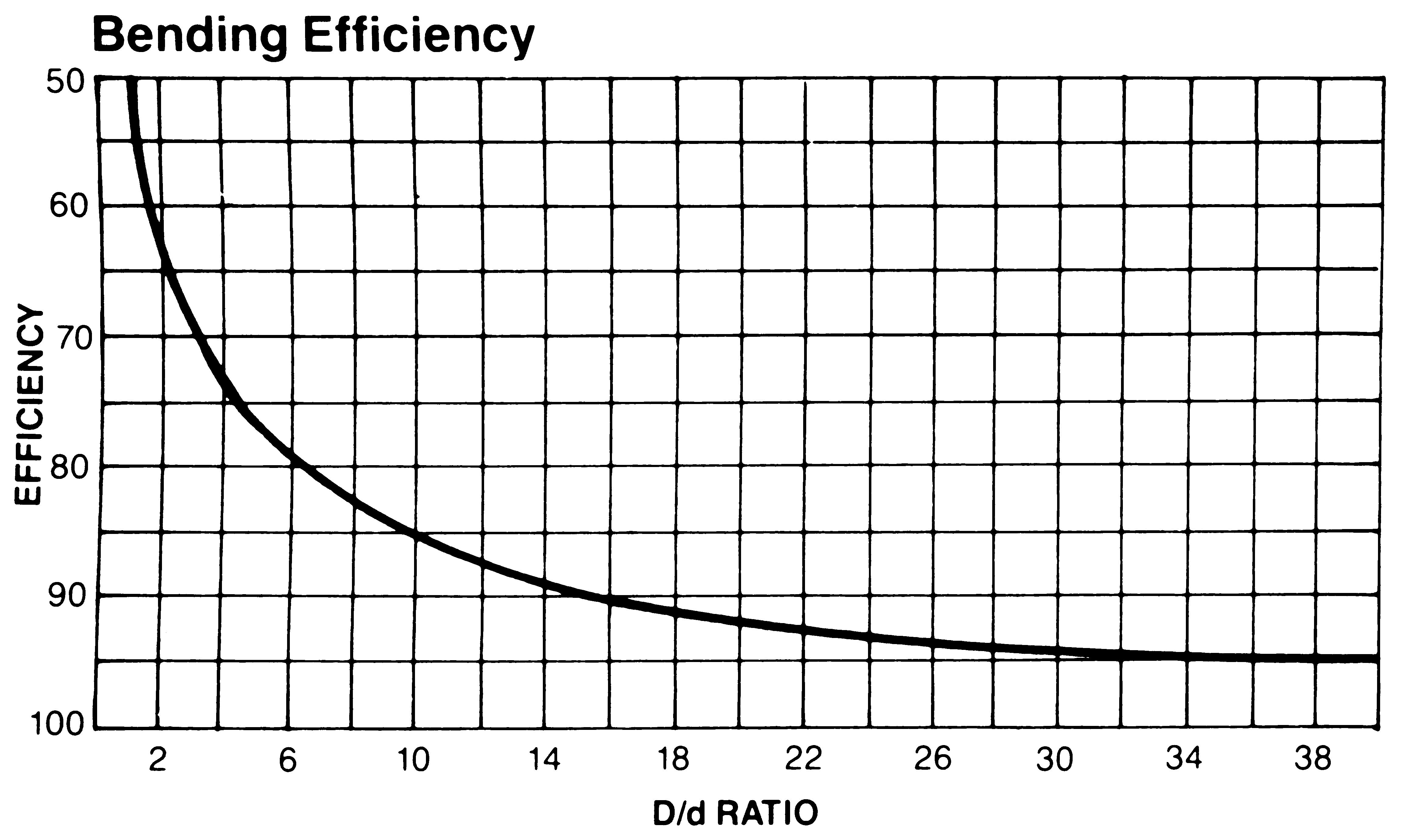
Efficiency falls as the D/d ratio becomes smaller. This curve, based on static test data only, illustrates the decline of bending efficiency for 6 x 19 and 6 x 37 classification ropes as the D/d ratio is reduced.
| Sheave Diameter Factors | |
| Suggested Minimum *D/d Ratios
*D-Sheave Tread Diameter d-Nominal Rope Diameter |
|
| Rope Construction | Minimum |
| 6 x 74 | 2 |
| 19×73 | 4 |
| 6×19 S3 | 4 |
| 6 x 21 FW | 30 |
| 6 x 25 FW | 26 |
| 6 x 36 FW | 23 |
| 8 x 25 FW | 21 |
| 6 x 41 WS | 21 |
To calculate the recommended or minimum sheave diameter for any given rope, find the rope construction and multiply the rope diameter by the value shown. (Ex.: Recommended sheave diameter for a 6 x 19 classification wire rope of 3/4″ diameter would be 51 x .75 = 38 1/4″)
Rope speed also affects fatigue life. Higher operating rates require larger sheaves.
Reverse bends from one sheave to another should be avoided. Other factors that affect bending fatigue life are load, number of cycles and condition of the sheaves and drums. Consult your local Branch for specific recommendations.

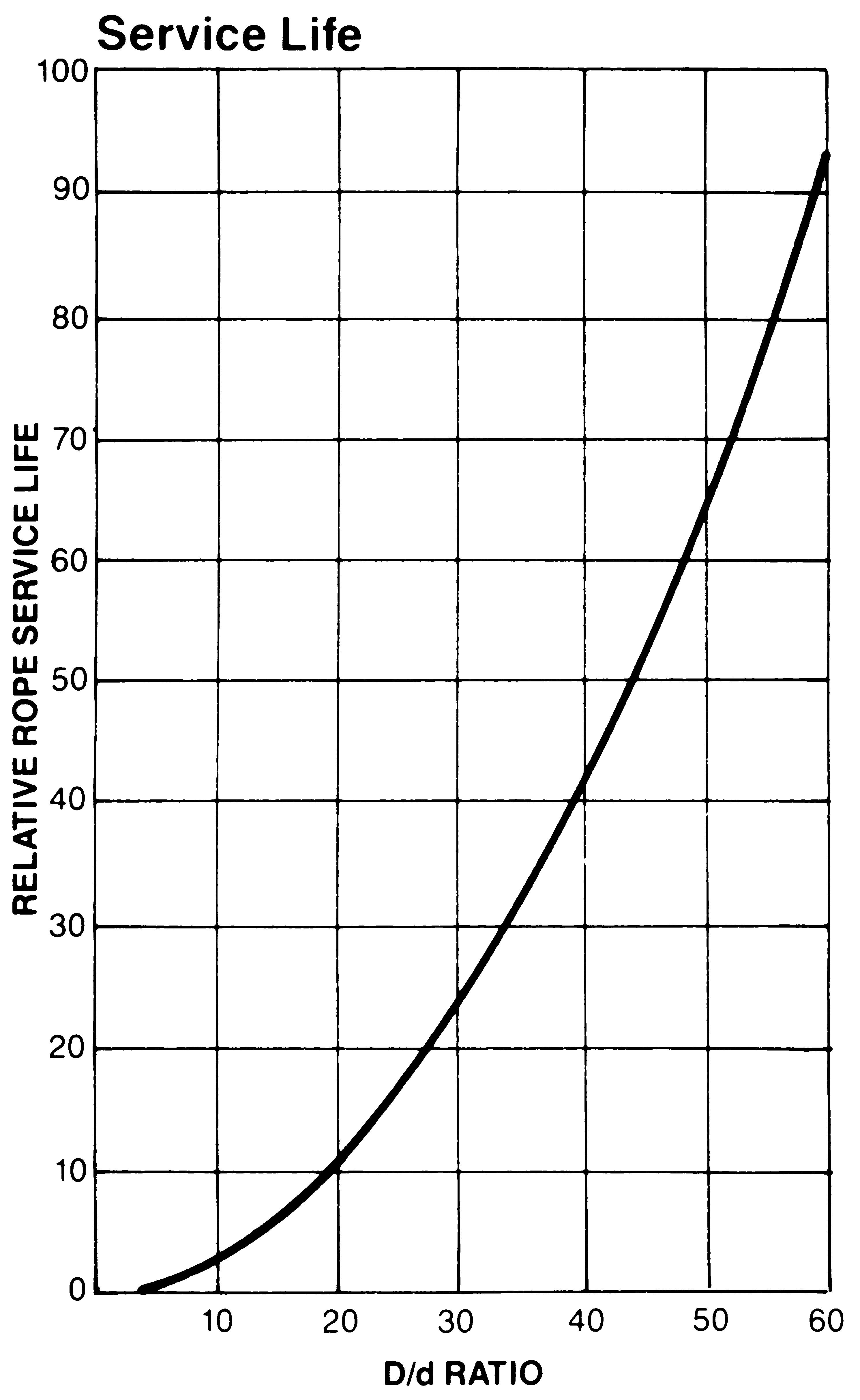
Service life increases as the D/d ratio becomes larger. This curve, based on bending and tensile stresses only, illustrates the relative performance increase.
Matching Grooves to the Wire Rope
Grooves should be spaced so that one wrap of rope does not rub against the next wrap during operation.
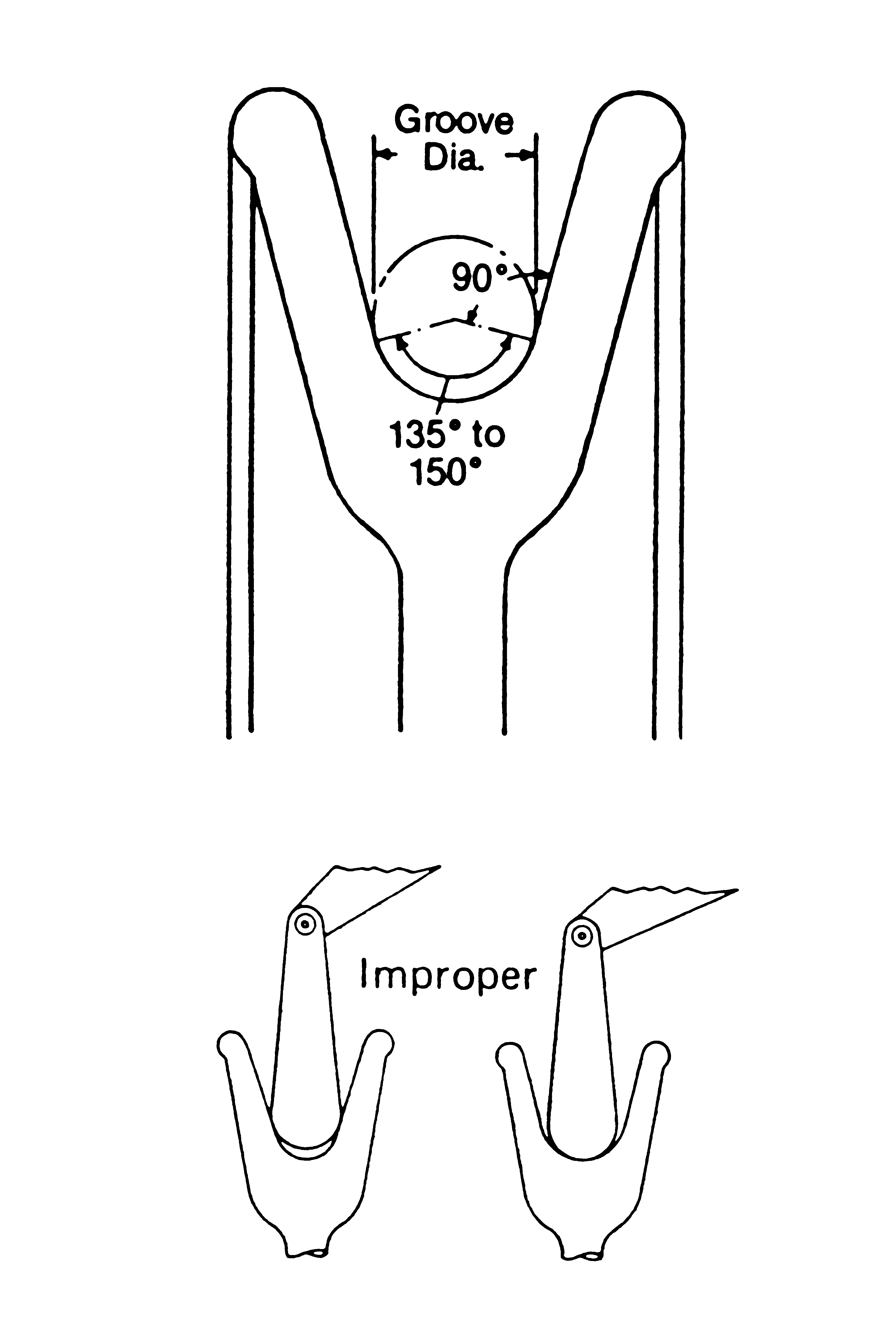
Grooves in sheaves and drums should be slightly larger than the wire rope to permit the rope to adjust itself to the groove. Tight grooves will cause excessive wear to outer wires; large grooves do not support the rope properly.
| Nominal Rope Diameter Inches | Tolerance | |
| Under | Over | |
| up to1/8 | -0 | +8% |
| over 1/8 to 3/16 | -0 | +7% |
| over 3/16 to 1/4 | -0 | +6% |
| over 1/4 | -0 | +5% |
As a rope is run through a groove, both become smaller. A used groove can be too small for a new rope; thus accelerating rope wear. A compromise between rope life and machining frequency must be made.


